LED Seven-Segment Display
Updated: 6/28/2025 Words: 0 words Reading time: 0 minutes
In the previous section, we learned how to control LED strips to produce different colors and effects. In this section, we will learn how to use LED seven-segment displays to form different numbers.
Preparation
Hardware
| Hardware | Description | Image |
|---|---|---|
| Creative Box Platform | 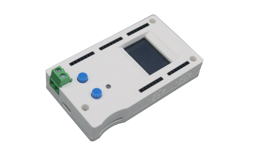 | |
| Seven-Segment Display Module | Creative Box Official Module | 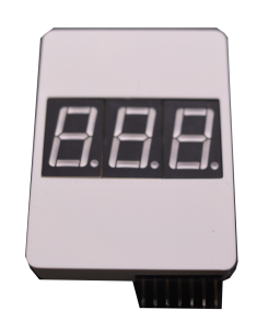 |
Software
| Software | Link | Description |
|---|---|---|
| Score Board System | Link | Official frontend application, can be directly loaded and used through the console. |
Video Tutorial
Seven-Segment Display
Connection
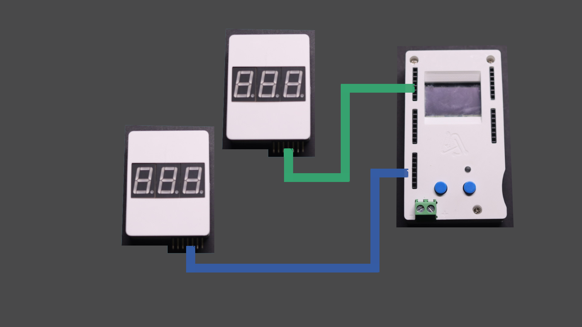
| Connection |
|---|
| ▀ Connect the first seven-segment display module to any pin header on the platform, here using platform pins 16-19 |
| ▀ Connect the second seven-segment display module to any pin header on the platform, here using platform pins 8-11 |
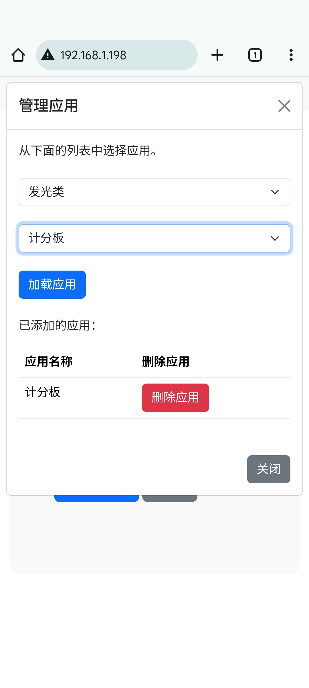
Usage
Open the Creative Box console and load the scoreboard application from the lighting category. Enter the application, select the connection pin numbers for the home team and away team seven-segment displays with the Creative Box. Click the corresponding scoring options. You can see the seven-segment displays showing the scores of the home team and away team.
| Creative Box Console | Load Application | Select Pin Numbers and Control |
|---|---|---|
 |  | 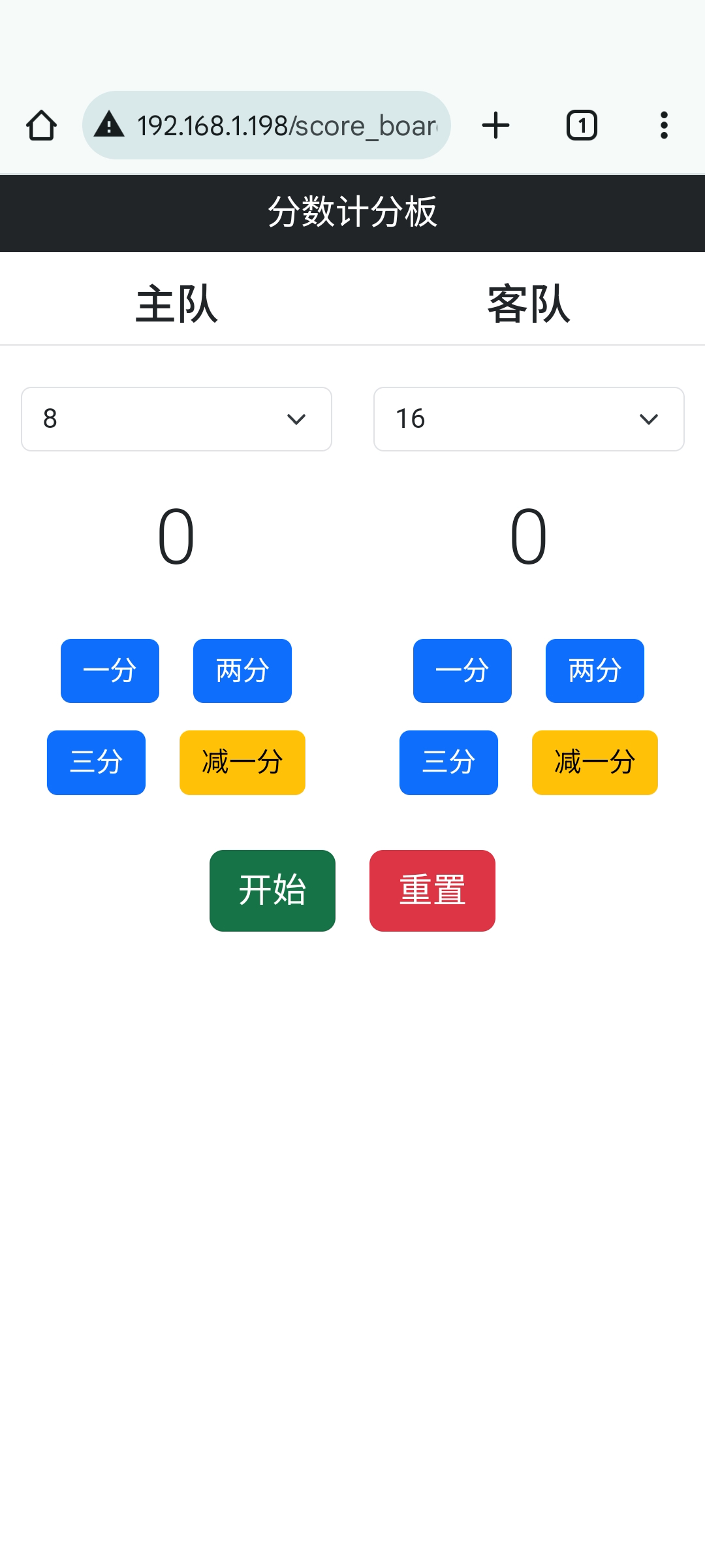 |
Principle
| Datasheet Download | Link |
|---|---|
| Seven-Segment Display | Link |
| Shift Register | Link |
Seven-Segment Display
A seven-segment display is a commonly used digital display device consisting of seven LEDs arranged in the shape of the number "8". Each LED represents a segment in the digit, and by turning these LEDs on or off, numbers from 0 to 9 can be displayed. Additionally, there is a dot-shaped LED in the bottom right corner of the seven-segment display. When two or more displays are connected together, this dot can represent a decimal point (DP).
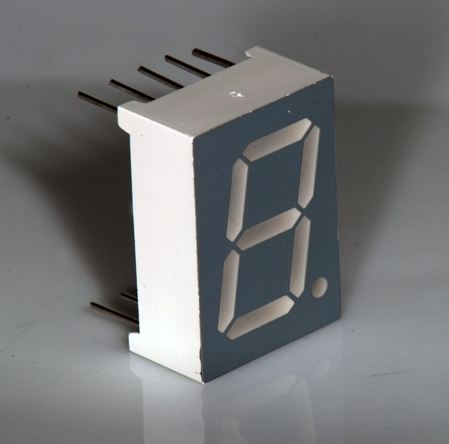
Each LED has its own separate pin. Simply applying power to the corresponding pin will light up the respective LED segment. Different combinations of LED segments form different numbers.

Like RGB LEDs, seven-segment displays are divided into common anode and common cathode types. In common anode displays, all LED anodes are connected together, while cathodes are connected to individual digit segments. In common cathode displays, all LED cathodes are connected together, while anodes are connected to individual digit segments. The diagram below shows the circuit diagram of a common anode seven-segment display:
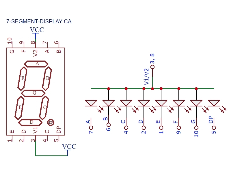
By controlling the lighting and extinguishing of each segment, we can flexibly display various numbers, letters, and symbols. Seven-segment displays can be seen in many electronic devices, such as clocks, counters, thermometers, etc. They provide a simple and intuitive way to display digital information.
Shift Register
A seven-segment display has eight LEDs, and we can assign one GPIO to each LED to control any LED. However, if we want to control multiple displays, this method would make the circuit very cumbersome. In this case, we need to use shift registers.
A shift register is a digital circuit component used to "move" data from input to output under the control of clock pulses. Shift registers have wide applications in digital systems, such as data storage, data transmission, display control, sequence generation, etc.
A shift register consists of several single-bit "D-type data latches", where each data bit can be logic "0" or "1", connected in series so that the output of one data latch becomes the input of the next latch, and so on. The number of data latches in a single shift register is usually determined by the number of bits to be stored, with the most common being 8-bit (one byte) wide, consisting of eight individual data latches.
Shift registers have four different operating modes, where the basic movement of data in the shift register includes:
- Serial Input Parallel Output (SIPO) - The shift register loads data serially bit by bit and outputs the stored data in parallel form.
- Serial Input Serial Output (SISO) - Data is serially "input" and "output" bit by bit in the shift register, shifting left or right one bit at a time under clock control.
- Parallel Input Serial Output (PISO) - Parallel data is loaded into the shift register simultaneously and output serially bit by bit under clock control.
- Parallel Input Parallel Output (PIPO) - Parallel data is loaded into the shift register simultaneously and transmitted to their respective outputs together under the same clock pulse.
Serial Input Parallel Output Shift Register
To control multiple LEDs with fewer GPIOs, we need to select a serial input parallel output shift register. Serial input means only one GPIO input signal is needed; parallel output means multiple LEDs can be lit simultaneously.
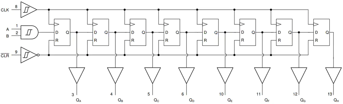
Taking the 4-bit serial input parallel output shift register in the diagram below as an example:
If logic high "1" is connected to the DATA input pin of FFA, then at the first clock pulse, the output of FFA and therefore the output of QA will be set to logic high "1", while all other outputs remain at logic low "0". Now assume the DATA input pin of FFA returns to logic low "0" again, giving us a data pulse or 0-1-0.
As clock pulses continue to be generated, the signal "1" continuously passes through the latches. When the fourth clock pulse arrives, the complete data value 0-0-0-1 is stored in the register. At this time, data can be read synchronously from the outputs QA to QD.
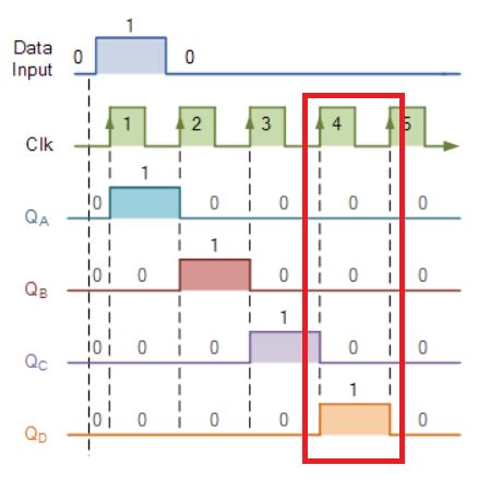
The table below shows the values of each latch at different clock pulses. At the fifth clock pulse, all outputs are at logic low "0" because the input remains at logic low "0".
| Clock Pulse | QA | QB | QC | QD |
|---|---|---|---|---|
| 0 | 0 | 0 | 0 | 0 |
| 1 | 1 | 0 | 0 | 0 |
| 2 | 0 | 1 | 0 | 0 |
| 3 | 0 | 0 | 1 | 0 |
| 4 | 0 | 0 | 0 | 1 |
| 5 | 0 | 0 | 0 | 0 |
74HC595 Shift Register
To control 8 LEDs simultaneously, we need an 8-bit serial input parallel output shift register. The schematic diagram shown below is the 74HC595 shift register we are using:
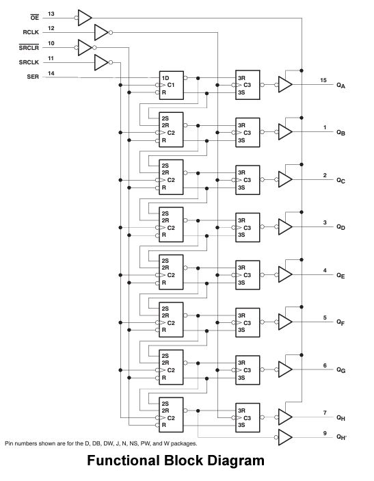
The function of each pin of the 74HC595:
- OE: Output enable pin, allows signal output when pulled low.
- RCLK: Signal output control pin, outputs parallel signal when pulled high.
- SRCLR: Register clear.
- SRCLK: Clock pulse signal.
- SER: Serial input signal.
Although the 74HC595 still requires 5 pins to control one seven-segment display, which seems not much different from traditional methods. However, if we have multiple displays, different registers can share the other four GPIOs except SER. For example, controlling three displays traditionally requires 24 GPIOs, while using shift registers only requires 7 GPIOs, greatly simplifying the circuit.
Next, we just need to understand which LEDs to light for different numbers, then transmit this 8-bit signal in parallel to the display to show specific numbers.
Truth Table
For seven-segment displays, we can create a truth table listing the various segments that need to be lit to produce decimal numbers from 0 to 9, as shown below:
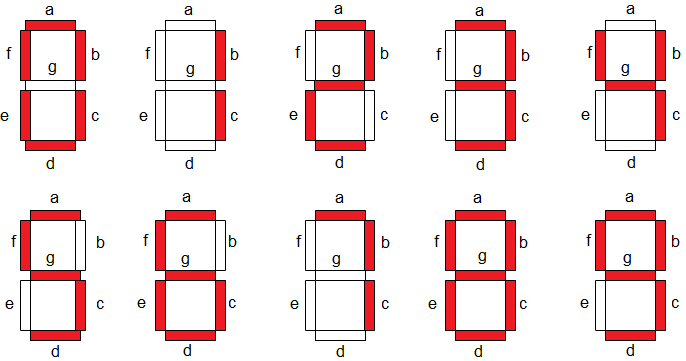
| Number | a | b | c | d | e | f | g |
|---|---|---|---|---|---|---|---|
| 0 | 1 | 1 | 1 | 1 | 1 | 1 | 0 |
| 1 | 0 | 1 | 1 | 0 | 0 | 0 | 0 |
| 2 | 1 | 1 | 0 | 1 | 1 | 0 | 1 |
| 3 | 1 | 1 | 1 | 1 | 0 | 0 | 1 |
| 4 | 0 | 1 | 1 | 0 | 0 | 1 | 1 |
| 5 | 1 | 0 | 1 | 1 | 0 | 1 | 1 |
| 6 | 1 | 0 | 1 | 1 | 1 | 1 | 1 |
| 7 | 1 | 1 | 1 | 0 | 0 | 0 | 0 |
| 8 | 1 | 1 | 1 | 1 | 1 | 1 | 1 |
| 9 | 1 | 1 | 1 | 1 | 0 | 1 | 1 |