Relay Module
Updated: 6/28/2025 Words: 0 words Reading time: 0 minutes
Relays are electromagnetic switches that use a low-power signal to control a higher-power circuit. This design effectively isolates the low-power signal from the higher-power circuit, protecting operators from harm and preventing equipment damage.
Additionally, common microcontrollers operate at low voltages. If you want to use these low-voltage microcontrollers to control high-voltage and high-current devices, such as lights, fans, luminaires, or other electrical appliances, you need to use a relay module to achieve this.
Preparation
| Hardware | Description | Image |
|---|---|---|
| Creative Box Platform | 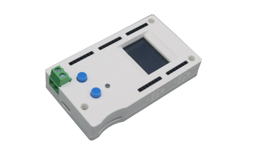 | |
| Power Signal Module | Included with Creative Box purchase | |
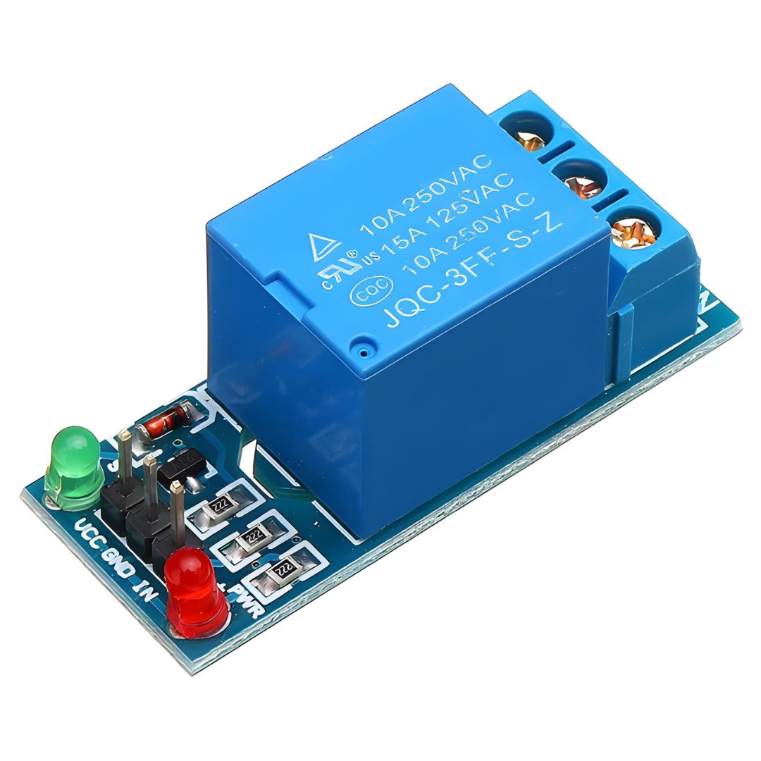
| Relay Module | Taobao Purchase Link | |
| Two-core Power Cable | Taobao Purchase Link | |
| Female Socket | Taobao Purchase Link |
Video Explanation
Relay and Power Control
Connection
Usage
Principles
The core of a relay is an electromagnet, which is essentially a coil of wire that becomes a temporary magnet when current passes through it. A relay can be thought of as an electrical lever that can be triggered by a relatively small current, which then produces a larger current to turn on another device.
The figure below shows how a relay connects two circuits.
Initially, both circuits are open, with no current flowing through them. When the switch in the first circuit is closed, a small current is produced, and the electromagnet is energized, creating a magnetic field around it. The energized electromagnet attracts the contacts of the second circuit, closing the switch and allowing a large current to flow through, thereby lighting up the bulb.
When the current in the first circuit stops flowing, the contacts in the second circuit return to their original position, the switch opens, and the bulb turns off.
Pinout
The figure below shows a typical single-channel relay module, with three high-voltage terminals (NC, COM, and NO) connected to the controlled device.
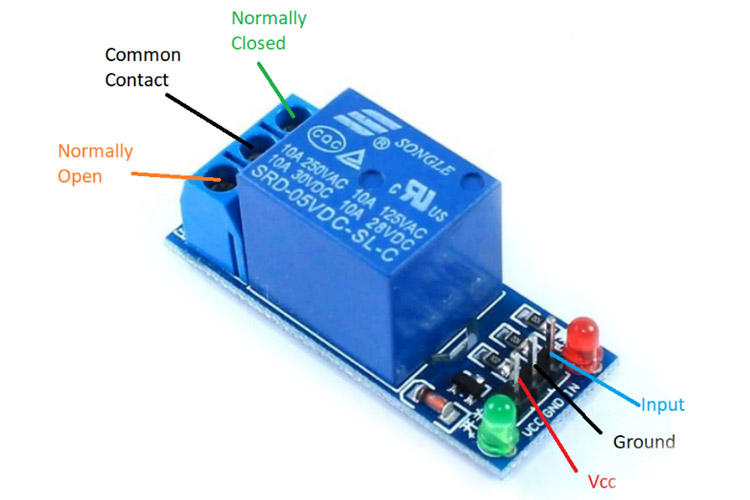
Specific pin descriptions are as follows:
| Pin Number | Pin Name | Description |
|---|---|---|
| 1 | Relay Trigger (input) | Input signal to activate the relay |
| 2 | Ground | 0V reference voltage |
| 3 | VCC | Supply voltage |
| 4 | Normally Open | Normally open terminal of the relay |
| 5 | Common Contact | Common terminal of the relay |
| 6 | Normally Closed | Normally closed terminal of the relay |
Normally (initial position), the COM terminal is connected to the NC terminal, and the NO terminal is open.
When current flows through the coil, the electromagnet is energized, causing the internal contacts of the switch to move. Then, COM connects to the NO terminal and disconnects from the NC terminal.
When current stops flowing through the coil, the internal contacts return to their initial position, reconnecting the NC terminal to COM and reopening the NO terminal.
In other words, a relay works similarly to a Single-Pole Double-Throw (SPDT) switch. Whether high-voltage devices are connected between the COM and NC terminals, or between the COM and NO terminals, depends on whether the device should normally be in an open or closed state.