Stepper Motor
Updated: 6/28/2025 Words: 0 words Reading time: 0 minutes
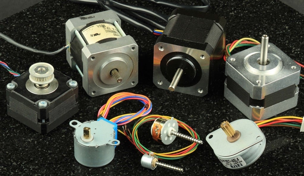
A stepper motor is a type of DC motor. Its characteristic is that the central shaft rotates a specific angle with each step.
Stepper motors are suitable for applications requiring low speed and high precision position control. For example, they can control paper feeding in printers, or adjust telescope angles to track stars. Stepper motors are also used in plotters and sensor positioning, among other fields.
Preparation
| Hardware | Description | Image |
|---|---|---|
| Creative Box Platform | 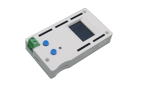 | |
| Stepper Motor and Driver | Taobao Purchase Link |
Video Explanation
Stepper Motor
Connection
Usage
Principles
Bill of Materials
| Hardware | Description |
|---|---|
| Sensor Platform | |
| ULN2003 Unipolar Motor Driver | Search for ULN2003 on shopping websites. Generally, ULN2003 driver chips are sold bundled with 28BYJ-48 motors. |
| 28BYJ-48 Unipolar Stepper Motor | The 28BYJ-48 motor has 5V and 12V versions. Since the platform supports 5V or 12V voltage output, both versions are supported. |
| Dupont Wires |
| Software | Description |
|---|---|
| Log in to the platform control page and load the Stepper Motor application (Category: Motor) | Supports clockwise or counter-clockwise rotation, different speed selections, and different drive modes. |
Circuit Connection
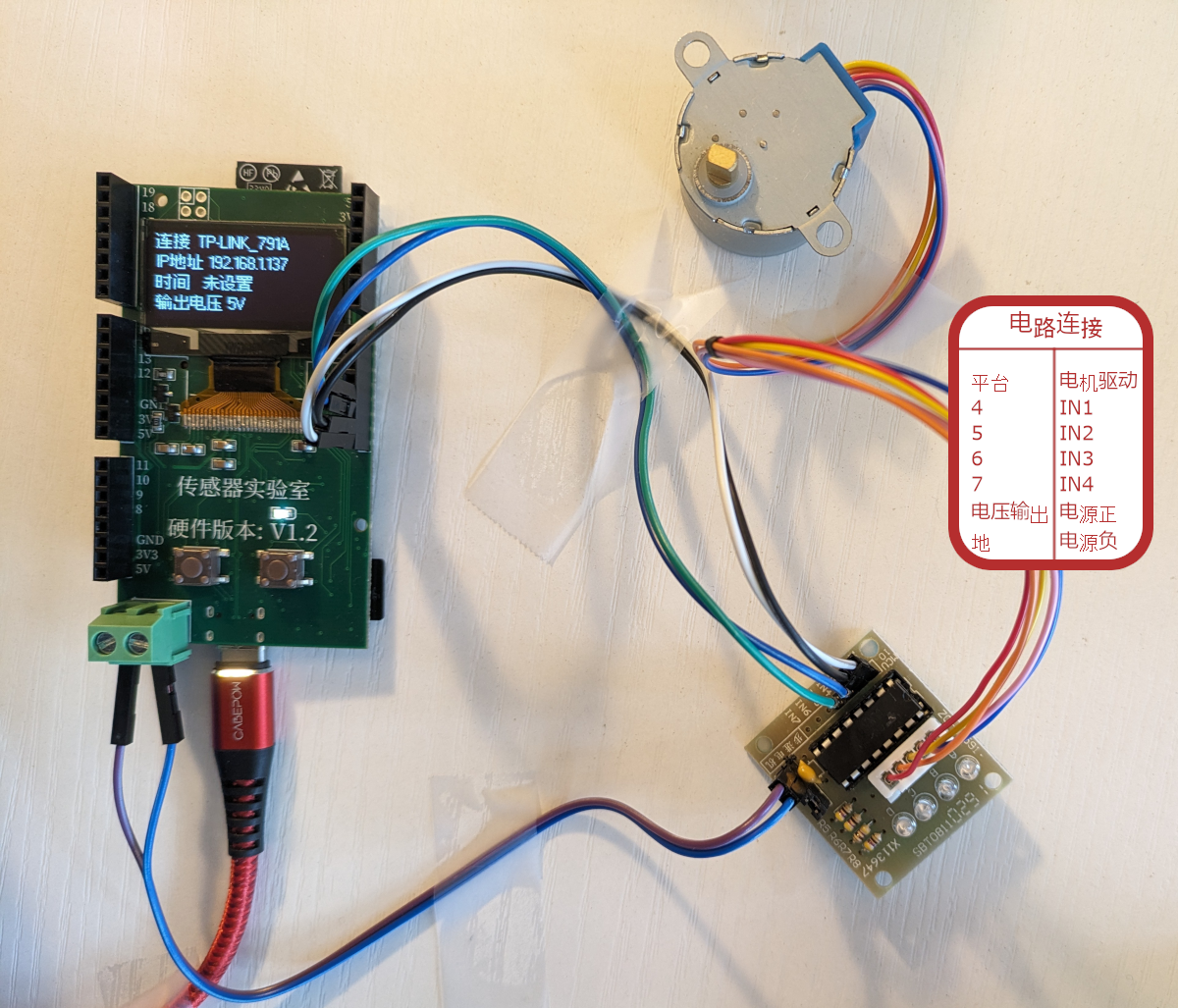
- The voltage supported by the 28BYJ-48 stepper motor is printed on the back of the motor. Here, the 5V version is used, and the voltage output value is set to 5V in the config.json file.
TIP
If using the 12V version of the stepper motor, please set the voltage output value to 12V in the config.json file, then use a Type-C PD supported power supply and ensure the voltage value on the screen is 12V.
- The phase signals (IN1, IN2, IN3, IN4) can be connected to any platform pin. The Python script used supports selecting pins connected to the platform from 0-3, 4-7, 8-11, 12-15, or 16-19.
Rotate!
Background and Principles
Steps
When clock pulses are applied to the circuit, a stepper motor rotates a specific angle, also known as a step. The number of steps per revolution determines the resolution of the stepper motor. The number of steps ranges from 4 to 400, with common values being 12, 24, and 48.
Resolution is usually expressed as 360°/steps. For a motor with 200 steps/revolution, the resolution is 360°/200 = 1.8°.
For a given stepper motor, the degrees per step (resolution) can be as small as 0.72° or as large as 90°. Common general-purpose stepper motor resolutions are 15° and 30° per step. The trade-off for higher resolution is speed and torque. For the same size, higher resolution means more steps per revolution, lower maximum speed, and lower torque.
How it Works
A stepper motor has a stationary part (stator) and a moving part (rotor). Coils are wound on the stator, while the rotor is either a permanent magnet or a variable reluctance iron core. The figure below shows a cross-section of a motor where the rotor is a variable reluctance iron core.
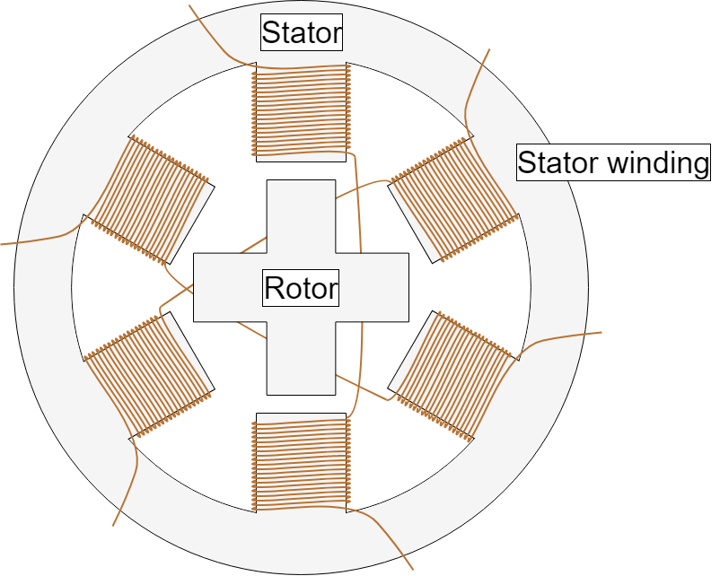
When one or more stator phases are energized, the current in the coils creates a magnetic field, and the rotor aligns with this magnetic field. By sequentially energizing different stator phases, the rotor can be made to rotate a specific angle to reach the desired final position.
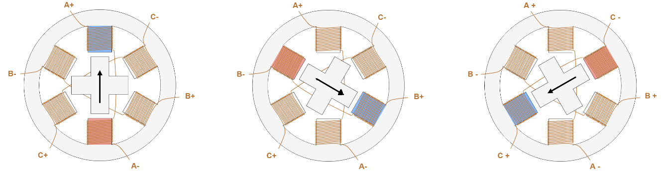
To illustrate, consider the initial state where stator A is energized, causing the rotor to align with its magnetic field. When stator B is energized, the rotor rotates 60° clockwise to align with the new magnetic field. When stator C is energized, the rotor rotates another 60° clockwise.
Classification
For stepper motors, there are basically three types of rotors: permanent magnet rotors (magnets), variable reluctance rotors (iron cores), and hybrid rotors. Hybrid rotors have a specific construction that is a mixture between permanent magnet and variable reluctance versions.
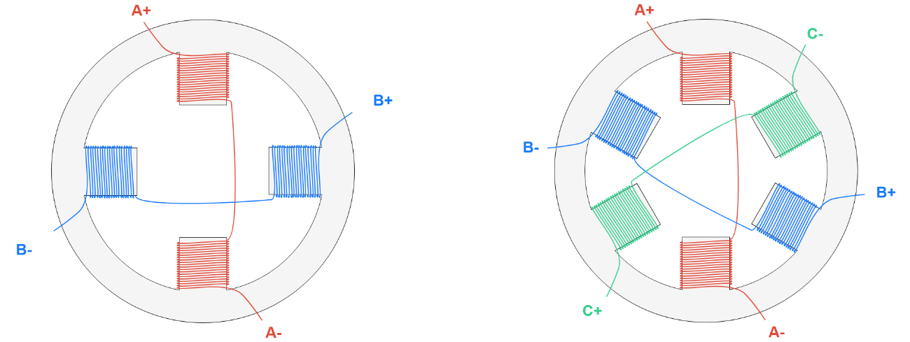
Key characteristics of stators include their number of phases and number of pole pairs. The number of phases is the number of independent coils, while the number of pole pairs indicates how many pairs of teeth each phase occupies. Two-phase stepper motors are the most commonly used, while three-phase and five-phase motors are less common.
The figure below shows a two-phase stator winding (left) and a three-phase stator winding (right).
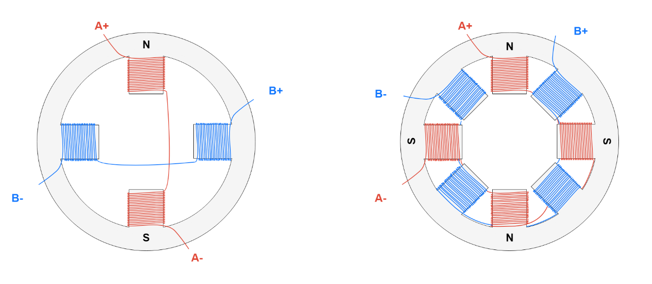
The figure below compares a two-phase, single pole-pair stator (left) and a two-phase, dual pole-pair stator (right). The letters indicate the magnetic field generated when a positive voltage is applied between A+ and A-.
Driving
When a motor rotates, it requires a significant current, which most microcontrollers cannot provide. Therefore, an additional stepper controller is needed to receive phase signals from the microcontroller and then drive the stepper motor.
Unipolar Drivers
Unipolar drivers have a common lead that will always be negative or grounded, and multiple phase leads. When a phase lead is positive, the corresponding stator generates a magnetic field, causing the motor to rotate. Unipolar drivers can be implemented with simple transistor circuits. The disadvantage is that less torque is available because only half of the coil can be activated at a time.
The simplest driver can consist of several transistors. By switching these transistors in sequence, the phases can be activated, causing the stepper motor to rotate. Unipolar drivers are relatively inexpensive but can only be used with unipolar motors. The following experimental section uses a unipolar motor and a unipolar driver.
Bipolar Drivers
Bipolar drivers use an H-bridge circuit to reverse the current flow through individual phases. With bipolar drivers, all coils can be used to drive the motor, thus providing greater available torque. Driving bipolar motors requires two complete H-bridges so that the current between phases can be reversed. Many affordable dual H-bridge chips are available, with the L293D being one of them.
| Unipolar Driver Chip ULN2003 | Bipolar Driver Chip L293D |
|---|---|
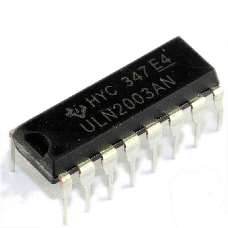 | 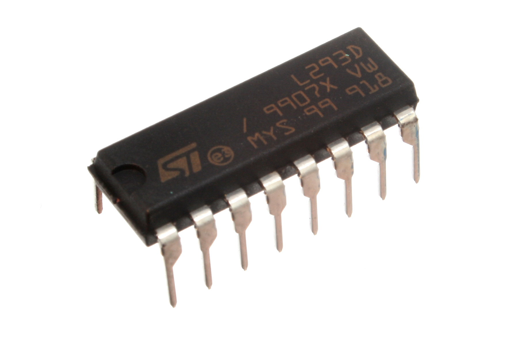 |
28BYJ-48 Unipolar Stepper Motor
Previously, we introduced the basics of stepper motors. Now let's delve deeper into the 28BYJ-48 stepper motor used in this experiment.
This motor is a unipolar stepper motor. Its internal structure is mainly divided into two layers: the upper layer is a 1:64 gear combination, designed to provide finer angular control. The lower layer consists of the rotor and stator.
| Image of the upper layer after disassembling the motor |
|---|
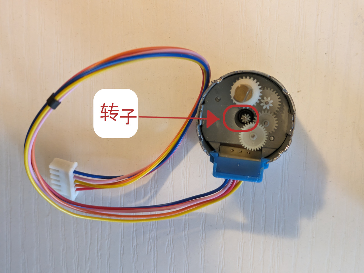 |
| Image of the lower layer after removing the upper layer. Rotor | Stator |
|---|---|
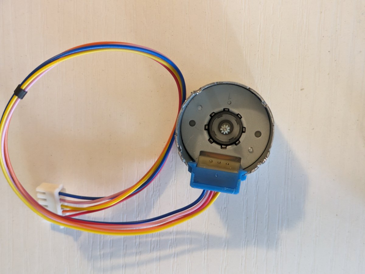 | 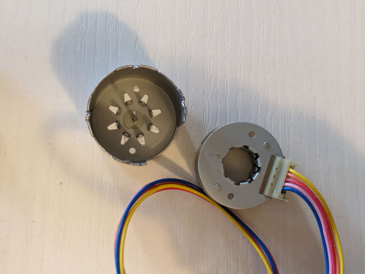 |
| Detailed photo of the stator |
|---|
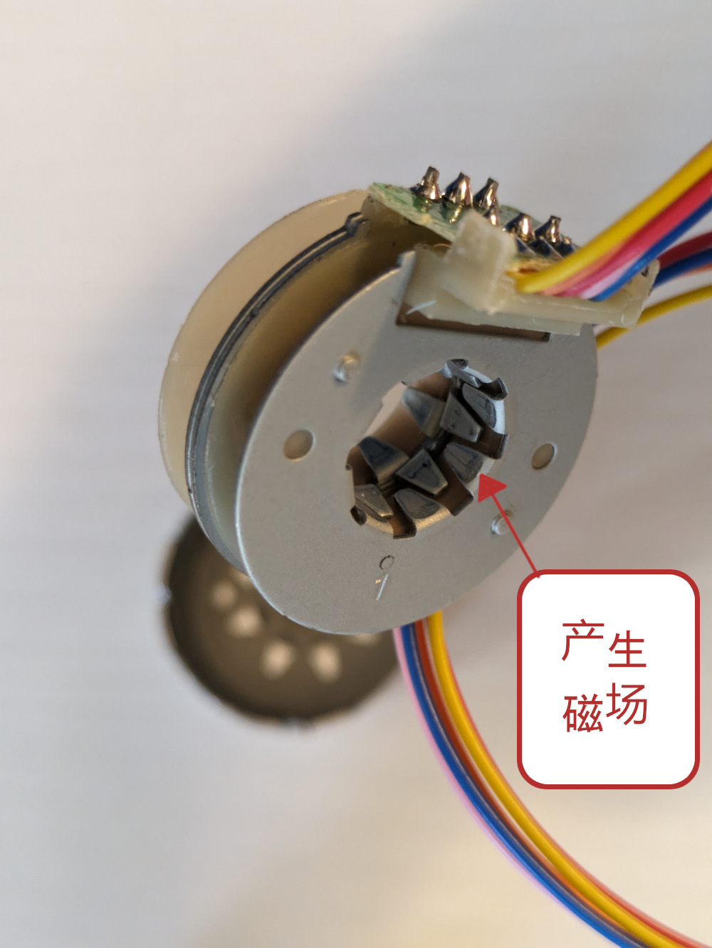 |
The stator is divided into two layers, each with upper and lower plates, and each plate has 8 triangular-like metal pieces. From the images, it can be seen that there are only three pieces in total across the upper and lower layers, with the missing piece being on the motor casing. Thus, the stator has a total of 8*4 = 32 triangles.
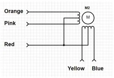
This motor has four phases (controlled by yellow, orange, pink, and blue wires, respectively). Each time one of the phases is set to high, the rotor can rotate to the position of the next triangle, so it takes 32 steps for the rotor to complete one revolution.
When the rotor rotates, it also goes through the gear combination in the upper part of the motor. We mentioned that the gear ratio is 1:64, so it actually takes 32*64 = 2048 steps to complete a 360-degree rotation, corresponding to an angle of about 360/2048 = 0.17 degrees per step.
The figure below is a simplified diagram of a unipolar stepper motor. When the next phase generates a magnetic field, the rotor rotates to the position corresponding to the next triangular metal piece.
| Simplified diagram of a unipolar stepper motor |
|---|
 |
Full Stepping and Half Stepping
When controlling stepper motors, we usually choose different control methods, commonly full stepping and half stepping. In addition, there are quarter stepping, eighth stepping, and so on.
The 28BYJ-48 can also achieve half stepping. Imagine when two adjacent phases simultaneously generate a magnetic field, the rotor will rotate to a position halfway between the two triangles. So, half stepping adds such an intermediate phase between two full steps.
Full stepping requires 32 steps for the rotor to complete one revolution. For half stepping, it requires 32*2 = 64 steps for the rotor to complete one revolution.
ULN2003 Unipolar Stepper Motor Driver Chip
ULN2003 integrates 7 transistors that help the microcontroller (i.e., the sensor platform) drive large currents to control the motor using small control signals.
There are many manufacturers of ULN2003, and they are very similar, usually interchangeable. For example, Jiangsu Changjing's ULN2003, Link.
| Driver Chip Schematic |
|---|
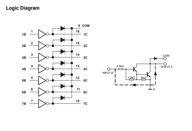 |
The schematic of ULN2003 is not complicated. The inputs are 1B-7B, and the outputs are 1C-7C. The output voltage is controlled by the input control signals. It can control up to 40V. Since the 5V version of the 28BYJ-48 motor is used here, the COM pin is connected to the 5V power supply.
Stepper motors have 4 phases. Connect the wires of each phase sequentially to 1B, 2B, 3B, and 4B.
Applications
Stepper motors are suitable for the following aspects:
- Positioning: Since stepper motors move in precise and repeatable steps, they excel in applications requiring precise positioning, such as 3D printers, CNC machines, camera platforms, and X, Y plotters. Some hard drives also use stepper motors to position the read/write head.
- Speed Control: Precise motion increments also allow for excellent control over rotational speed, suitable for process automation and robotics.
- Low-Speed Torque: Ordinary DC motors do not have much torque at low speeds. Stepper motors have maximum torque at low speeds, making them a good choice for applications requiring low speed and high precision.