Accelerometer and Gyroscope
Updated: 6/28/2025 Words: 0 words Reading time: 0 minutes
We can use compass applications on our phones to know the current direction, or use stargazing software to display constellations at different positions. This is because phones are equipped with accelerometers.
An accelerometer is an electronic device used to measure object acceleration (including static gravitational acceleration and dynamic motion acceleration), widely used in consumer electronics, automotive, industrial control, medical devices, and other fields. Its core function is to detect the motion state of objects in three-dimensional space (X/Y/Z axes) and convert acceleration signals into electrical signal outputs.
A gyroscope is a sensor used to measure angular velocity (rotation rate) of objects, capable of detecting rotational motion around the X/Y/Z axes.
Preparation
Hardware
| Hardware | Description | Image |
|---|---|---|
| Creative Box Platform | 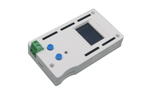 | |
| MPU6050 Accelerometer Module | Taobao Purchase Link | 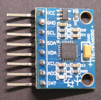 |
| Dupont Wires | Taobao Purchase Link, please select male-to-female type |
Software
| Software | Link | Description |
|---|---|---|
| Accelerometer Application | Link | Official frontend application, can be loaded and used directly through the console. |
Connection
| Connection |
|---|
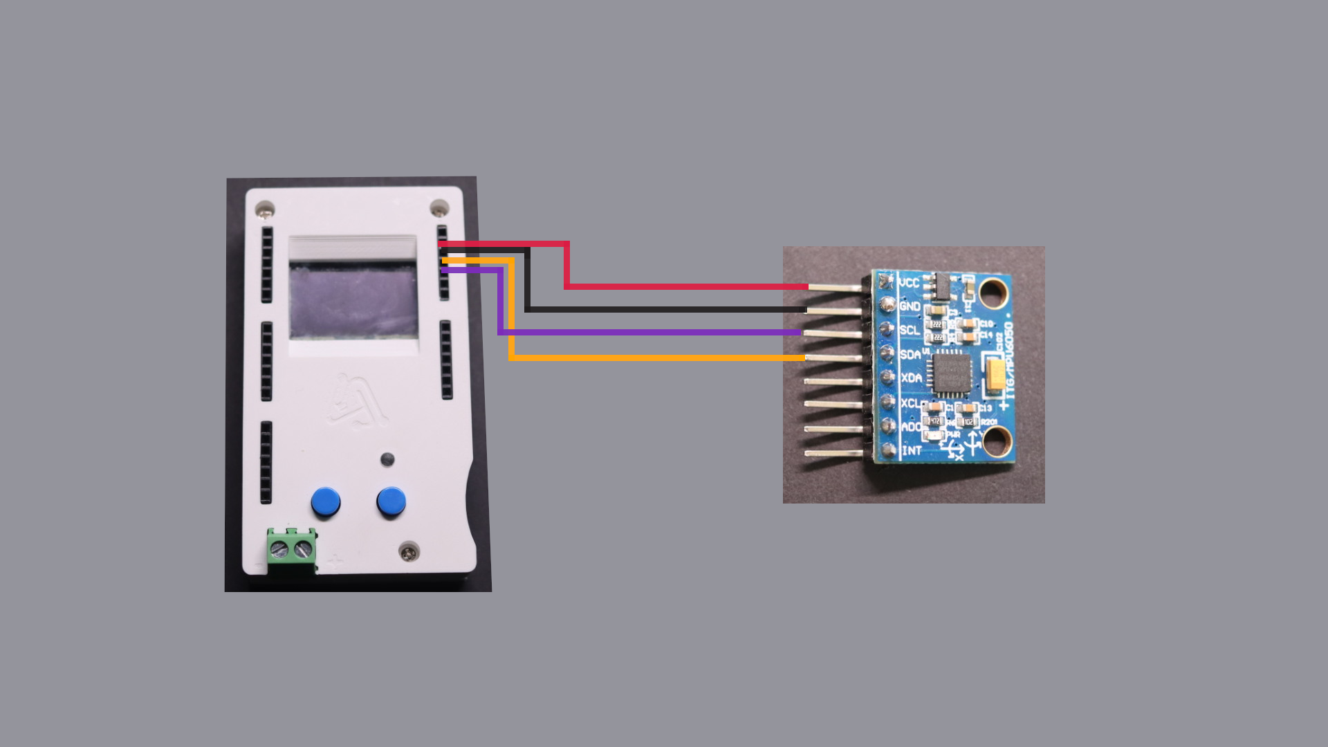
| ▀ Connect MPU6050's VCC pin to the platform's 3.3V power supply. |
| ▀ Connect MPU6050's GND pin to the platform's GND. |
| ▀ Connect MPU6050's I2C bus SDA pin to any pin on the platform, the diagram shows pin 0. |
| ▀ Connect MPU6050's I2C bus SCL pin to a platform pin, this platform pin needs to be the next one after the SDA pin, so the accelerometer application can get the correct I2C bus pins. |
Usage
Note
The following step screenshots are from mobile browser to conveniently show each step.
Due to large data volume, the mobile web cannot achieve the best graphical display effect.
It's recommended to use a computer browser for the accelerometer application, following the same steps.
| Creative Box Console | Load Application | Select Pin Number and Range | Click Start Button and Shake MPU6050 to Get Acceleration and Angular Velocity Readings on X,Y,Z Axes, Press Stop Button to End |
|---|---|---|---|
 | 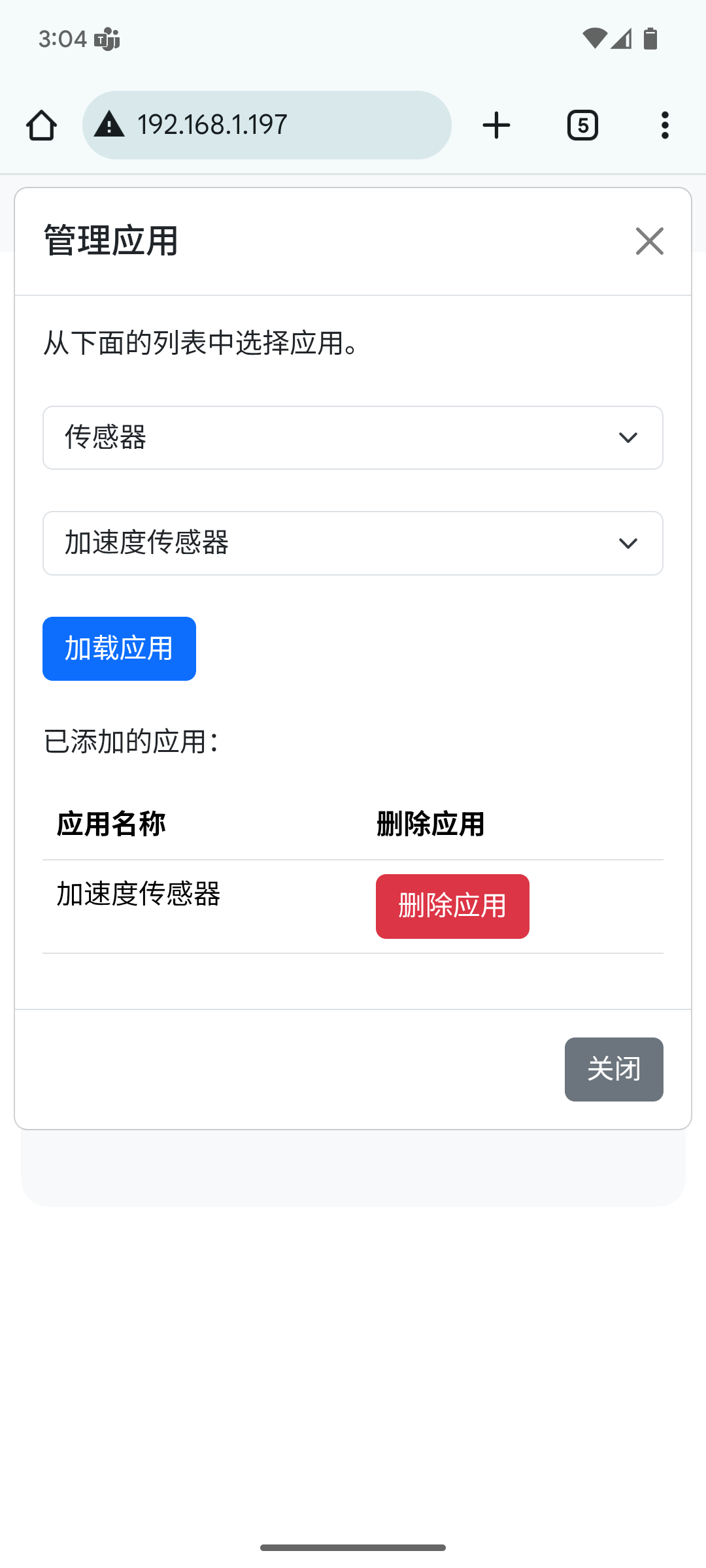 | 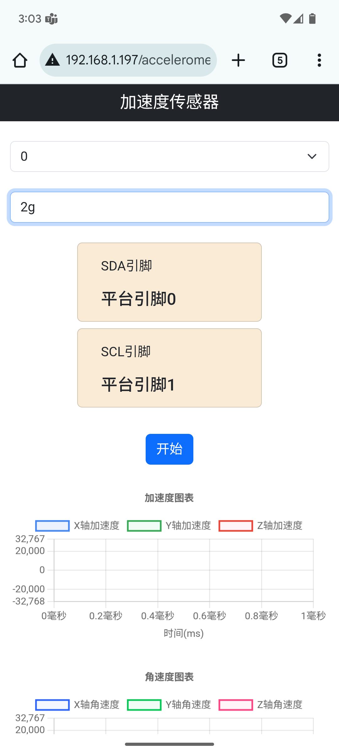 | 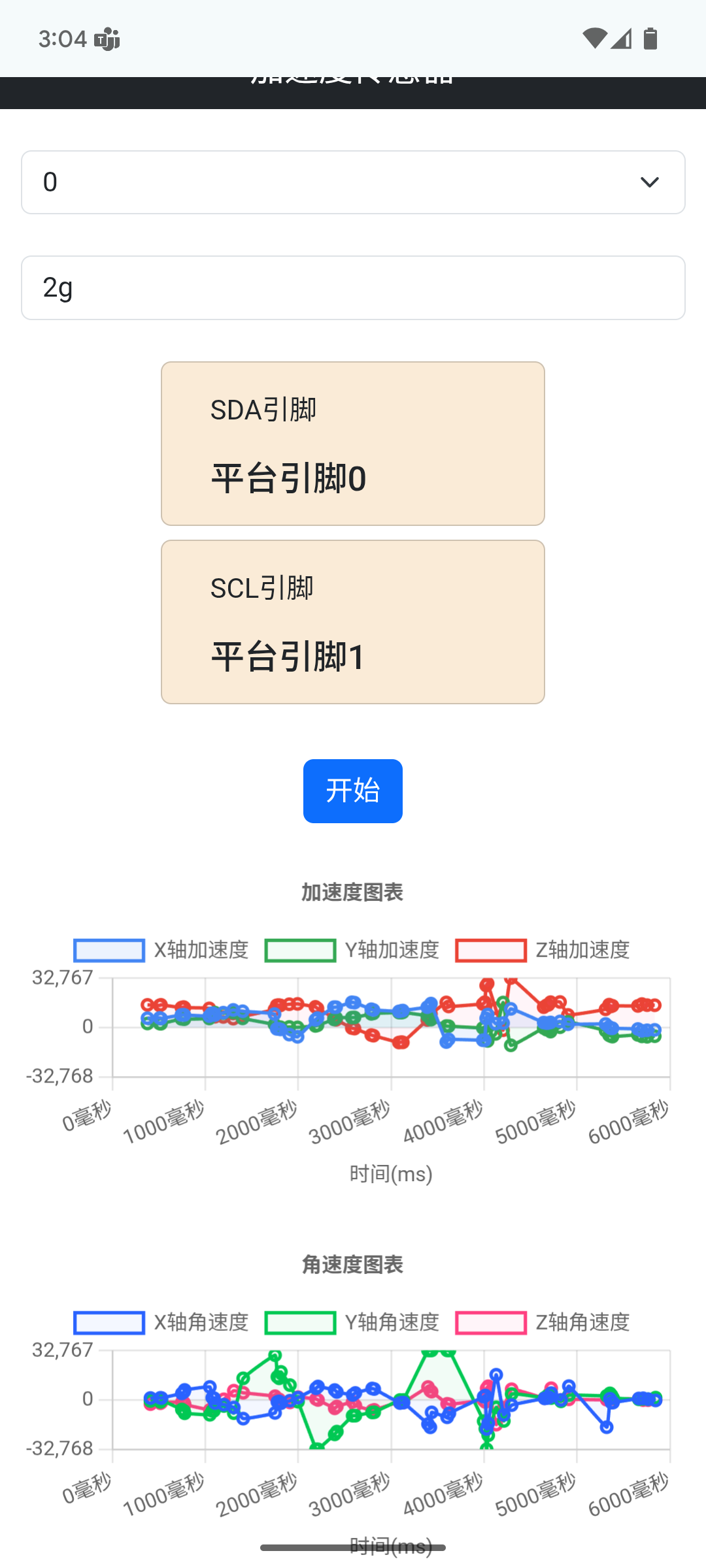 |
Principles
Accelerometers can measure static or dynamic acceleration. Static acceleration is a constant force acting on an object, such as gravity or friction. These forces are largely predictable and uniform. For example, acceleration due to gravity is almost constant at every point on Earth, approximately 9.8 meters/second².
Dynamic acceleration forces are non-uniform. Car crashes are excellent examples of dynamic acceleration. When a car crash occurs, the change in acceleration is sudden. Accelerometers work by detecting acceleration and converting it into electrical signals.
MPU6050
MPU6050 can monitor acceleration! It's a 6-axis inertial measurement unit (IMU) that integrates a 3-axis accelerometer and 3-axis gyroscope, capable of simultaneously measuring linear acceleration and angular velocity.
| Parameter Name | MPU6050 |
|---|---|
| I2C Address | 0x68 (default) or 0x69 |
| Range | Selectable 2g, 4g, 8g, or 16g |
Reference Datasheet Download
| Datasheet Download | Link |
|---|---|
| MPU6050 Datasheet | Link |
| MPU6050 Registers | Link |
I2C Communication
The controller platform interacts with MPU6050 through the I2C bus, configuring and reading acceleration and angular velocity values by reading and writing different registers in MPU6050.
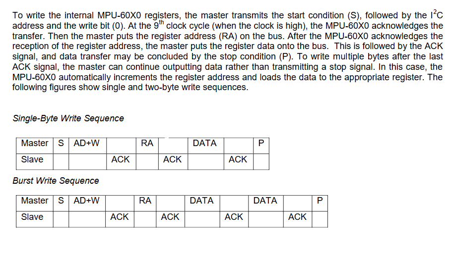
The following diagram (page 35 of the datasheet) shows how to perform I2C write operations. The platform first sends a start bit, then the MPU6050 address and write operation bit, then MPU6050 pulls the data line low for ACK. After that, the platform sends the register address and data to be written.
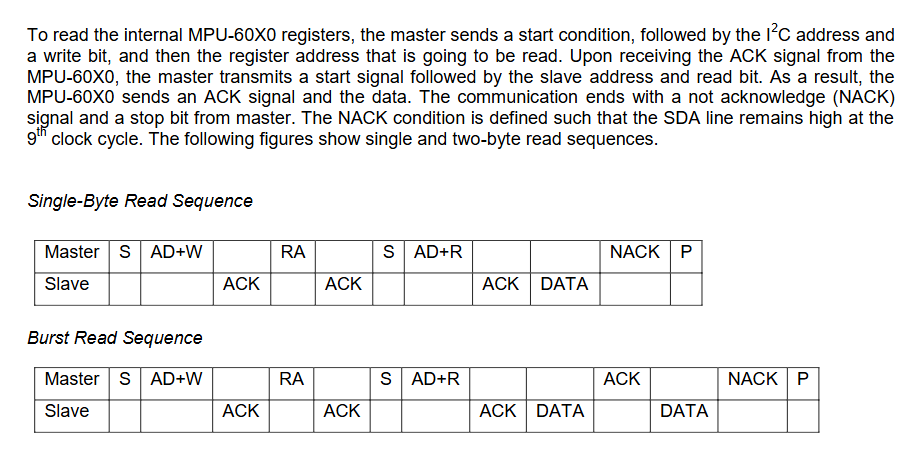
The following diagram (page 36 of the datasheet) shows how to perform I2C read operations. You need to first write the register address to be read, then perform the read operation.
Reading Acceleration and Angular Velocity Values
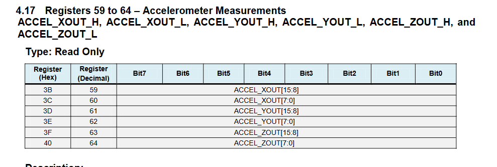
Acceleration and angular velocity values are stored in registers 59 to 72. First read the values of these 14 registers through the platform, then perform calculations to get acceleration x,y,z axis and angular velocity x,y,z axis readings. Each reading is 16 bits.
The following screenshot (page 29 of the MPU6050 register manual) lists the accelerometer register information.
Here's the request to read acceleration, temperature, and angular velocity through the platform, starting from register 59 and reading 14 data sequentially:
{
  "event":"now",
  "actions":[["i2c",0,"write",0,1,100,104,-1,-1,1,59],["i2c",0,"read",0,1,100,104,-1,-1,14]]
}The return value is as follows, through calculation the acceleration X,Y,Z axis values are -192, -3544, 14968 respectively. Angular velocity X,Y,Z axis values are -134, 329, -186 respectively.
{
  "errorcode":0,
  "result":[[1],[255,64,242,40,58,120,242,192,255,122,1,73,255,70]]
}Selecting Appropriate Range
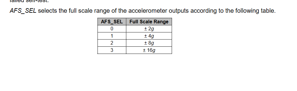
You need to pre-judge the maximum values that acceleration and angular velocity might reach to select the appropriate range. MPU6050 provides 4 range selections: 2g, 4g, 8g, and 16g.
Larger range selection means lower measurement accuracy but wider measurement range, while smaller range selection means higher measurement accuracy but narrower measurement range.
Range selection is done through acceleration and angular velocity configuration registers (the following screenshot is from page 15 of the datasheet). You can select the appropriate range in the accelerometer application.
Here's the request to modify acceleration and angular velocity range registers through the platform, setting both acceleration range and angular velocity range to 2g:
{
  "event":"now",
  "actions":[["i2c",0,"write",0,1,100,104,27,-1,1,0],["i2c",0,"write",0,1,100,104,28,-1,1,0]]
}Selecting Appropriate Accelerometer
When selecting an accelerometer, besides general power consumption and communication interface considerations, you also need to consider force measurement range and some additional features.
Most accelerometers have selectable force measurement ranges. These ranges can vary from ±1g to ±250g. Generally, the smaller the range, the more sensitive the accelerometer readings. For example, to measure small vibrations on a desktop, using a small-range accelerometer will provide more detailed data than using a 250g range (250g range is more suitable for applications like rockets).
Some accelerometers include features such as tap detection (useful for low-power applications), free-fall detection (for active hard disk protection), temperature compensation (to increase accuracy without GPS), and 0g range sensing. When purchasing accelerometers, you also need to consider whether these features are needed.
There are also some IMUs (Inertial Measurement Units) available that can integrate accelerometers, gyroscopes, and occasionally magnetometers into a single IC package. These are commonly used in motion tracking applications and drone navigation systems.